|
Home \ Instrumentation ALMA Taiwan \ MZM LORTM
MZM Local Oscillator Reference Test Module (LORTM)ASIAA has developed a Local Oscillator Reference Test Module (LORTM) for use as a test source at the East Asia Front End Integration Center (EA-FEIC). This instrument is based on a Mach-Zehnder Modulator (MZM) technology to generate 2 sets of simultaneous references, one for the Local Oscillator (LO) and the other for the Reference Test signal. Since delivery in August of 2011, this unit has been in constant use in the line 1 chamber at EA-FEIC. This instrument is also used to run the WCA swept lock tests for the Front End being tested in the line 2 chamber, since the swept lock tests using the MZM-LORTM is significantly faster than the existing LORTM provided by ALMA-NA. 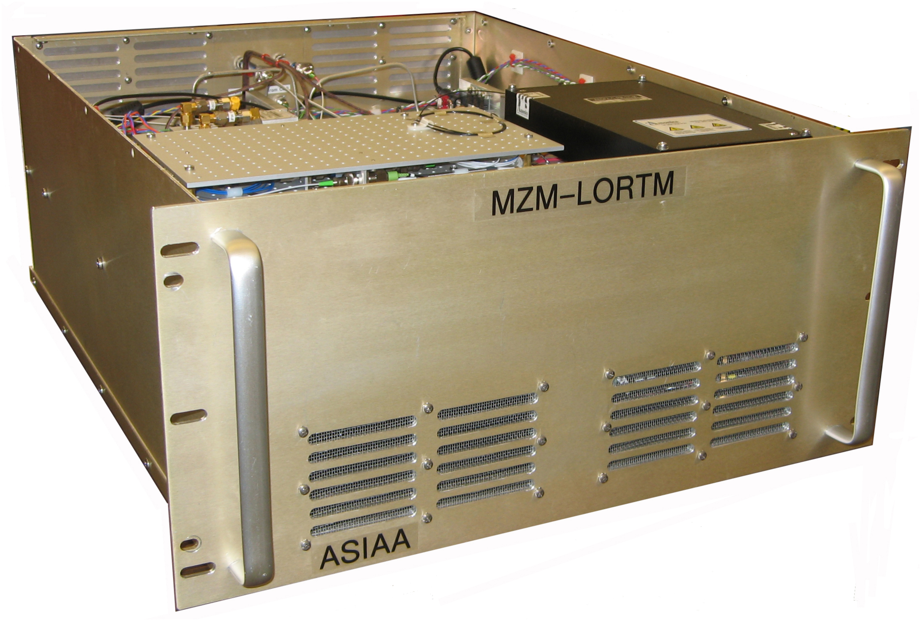 Figure 1. MZM-LORTM - Delivered to EA-FEIC Taiwan in August 2011 as part of the Front End Test and Measurement Setup (FETMS). This unit replaced a TeraXion LORTM loaned to ASIAA by ALMA-NA.  Figure 2. Internal view of MZM-LORTM. Left photo – bottom of chassis, includes the ADAM controller (blue box), Miteq IF power amplifier (black box, upper right), the 1556.21 nm reference laser (TeraXion), and the DC power supplies. Right photo - view of top, includes the two Centellax RF power amplifiers (green circuit boards), MZ1 & MZ2, the 2 FBG assemblies (located on 2 plates below the EDFA), combiner plate (located below the rectangular aluminum plate), and the EDFA (black box, lower right). Mechanical packaging of the MZM-LORTM is shown in Figure 1 and Figure 2. The unit dimensions are 48.3 x 22.2 x 55.9 cm (width, height, depth), weight 21.4 kg, and power consumption of 131 W. The unit is designed to mount directly onto the tilt table that moves in elevation from 0 to 90 degrees. Forced air cooling is provided to the lower deck using 2 intake fans on the rear panel and exhausts on the front panel. For the purpose of phase stability, all optical components with the exception of the laser were located on the upper deck and sealed from convection air. Thermal cooling of the RF Centellax amplifiers and MZ1/MZ2 were via conduction through the deck plate. The power dissipation of MZ2 required active cooling via a Thermo Electric Cooler (TEC) device. A simplified block diagram for the MZM-LORTM is provided in Figure 3. A narrow line width input laser (1556.21 nm) is split into 2 signals by an optical power divider and provided to MZM devices MZ1 and MZ2. MZ1 port C is operated in Full-bias mode and generates a pair of optical tones spaced by 4 x RF, where RF is the Radio Frequency input reference (15 – 31 GHz). The Lower Side Band (LSB) tone is eliminated by FBG (Fiber Bragg Grating) Plate 1. MZ2 ports A and B are operated in Null-bias mode, both of which internally generate a pair of tones closely spaced by 2 x IF, where IF is the Intermediate Frequency input reference (0.2 – 3.0 GHz). In addition, MZ2 port C is operated in Full-bias mode and generates a set of 6 optical tones. The pair of Upper Side Band (USB) tones are eliminated by FBG Plate 2. The Combiner Plate combines the 2 sets of signals and a set of FBG filters are used to eliminate the laser carrier tones. An EDFA (Erbium Doped Fiber Amplifier) provides gain and amplitude leveling to compensate for lower MZM modulation indicies at higher RF frequencies. An optical Band Pass Filter (BPF) is used to remove a large portion of the optical noise pedestal introduced by the EDFA. The final output signal is divided to provide 2 optical reference signals to the LO and Reference Test signal sources. All components and optical fibers are Polarization Maintaining (PM) in order to meet the Polarization Extinction Ratio (PER) requirement.  Figure 3. Simplified block diagram of MZM-LORTM unit. A laser is used to generate a pure tone at 1556.21 nm and is split by an optical power divider. The upper optical path is RF modulated via MZ1 to produce 2 optical output tones, however, the LSB is removed via FBG filters and only the USB is kept. The lower path is RF & IF modulated to produce 6 optical tones, the USB tones are removed and only the LSB are kept. The Combiner Plate sums the upper and lower optical paths, removes 3 central tones via FBG filters to produce the 3 desired optical tones as shown in the lower right. The underlying technology used within the MZM-LORTM are MZM devices, MZ1 and MZ2, and is illustrated in Figure 4. The optical input is split into two optical paths and recombined after applying the phase modulation. The interferometer is composed of a Lithium Niobate substrate with a refractive index that changes with the applied electrical field and is the basis of the phase modulation. At the output, complete destructive interference will result with an applied phase of 180 degrees across one arm with respect to the other. The MZ devices are composed of 3 such interferometric arms, each one being controlled by separate DC biases, supplied at ports A, B and C. Each sub-MZM can be operated in 2 modes as follows:
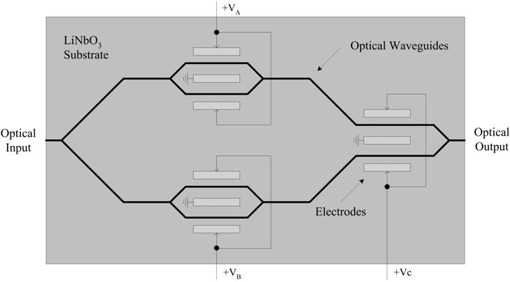 Figure 4. Internal configuration of Mach-Zehnder Modulator devices, MZ1 and MZ2. This device consists of 3 separate sub-MZMs on a single substrate. MZ1 utilizes only port C for RF modulation in Full-bias mode to produce a pair of optical tones spaced by 4 x RF. For MZ2, ports A and B are IF modulated in Null-bias mode to produce a pair of optical tones spaced by 2 x IF, and in addition, port C is RF modulated in Full-bias mode to produce a total of 6 optical tones (2 closely spaced LSB tones, 2 closely space central tones, and 2 closely spaced USB tones). Spectral outputs from the MZM-LORTM are shown in Figure 5. In this example, IF and RF are set to 3.0 GHz and 25.75 GHz, respectively. The result is an LO signal of 4 x RF – IF = 100 GHz, and Reference Test signal = 4 x RF + IF = 106 GHz. 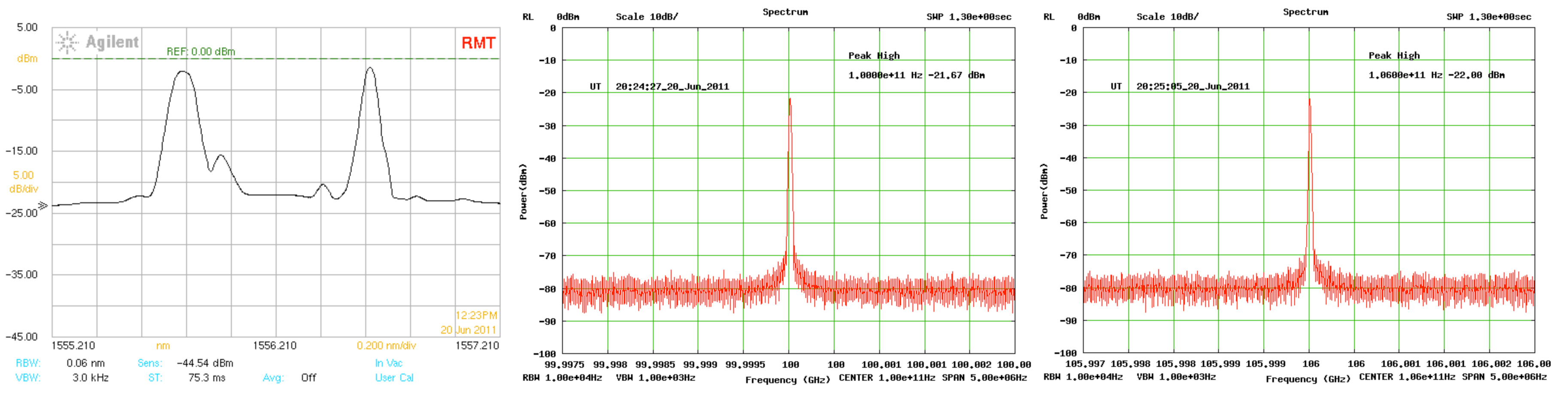 Figure 5. Optical and RF output spectra for 100/106 GHz: Left - optical output of LORTM, note the 2 LSB tones appear as 1 due to limited resolution bandwidth of the spectrum analyzer; Center – 100 GHz LO output from photomixer; Right – 106 GHz Reference Test signal output from photomixer. Referring back to Figure 3, the J3 and J4 Test points are used to monitor the raw unfiltered outputs from MZ1 and MZ2, respectively. These Test Point outputs are connected to either an Optical Spectrum Analyzer (OSA) or an optical power meter where it forms part of a closed loop software code which restores the original DC operating point of the MZM devices. The MZM suffers from slow monotonic DC drift with time because of space charge accumulation at the electrodes and results in the growth of undesired optical harmonic spurious tones. It is therefore necessary to periodically “rebias” the MZM devices by applying negative voltages at ports A, B, and C for extended periods of time to disperse the space charges. The MZM-LORTM is part of a suite of instruments that comprise the Front End Test and Measurement System Setup (FETMS) used for Front End receiver performance verification. The MZM-LORTM itself underwent an entire set of sub-system performance verification tests documented under ALMA EDM FEND-40.09.03.00-0405-A-REP. Figure 6 shows the results of an automated Warm Cartridge Assembly (WCA) lock test for Band 7 using the MZM-LORTM. It should be noted that the MZM-LORTM provides a distinct advantage over the ALMA-NA unit in terms of tuning speed for swept lock tests. The results of long-term phase stability tests are shown in Figure 7 using a modified Beam Scanner Test Source (BeaSTS). Note the extremely stringent requirement of 5 fsec Allan Deviation imposed on the resultant 6 GHz IF signal (106 – 100 = 6 GHz) and corresponds to a peak-to-peak phase variation of less than 1 degree over intervals of 300 seconds. 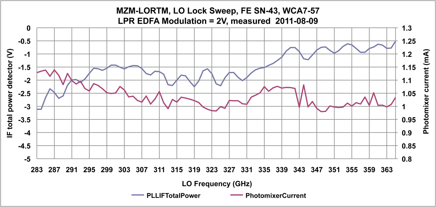 Figure 6. Band 7 swept lock tests. Plot of WCA IF total power and photomixer current versus frequency. Note the wide sweep range from 283 to 365 GHz. 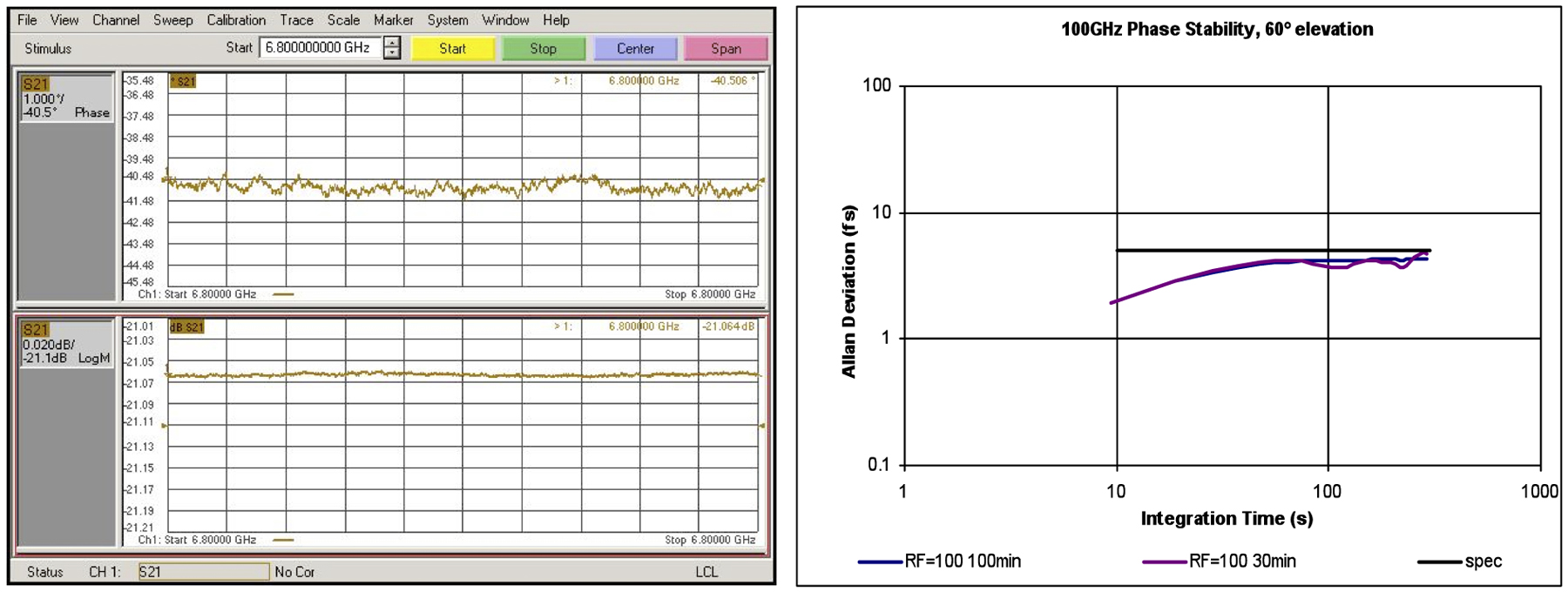 Figure 7. Long term phase stability measurement at 100/106 GHz, 60 degree tilt table angle: Left upper plot is phase at 1 degree/division, left lower plot is amplitude at 0.02 dB/division, 100 minutes duration; right plot is associated Allan Deviation performance from 10 – 300 seconds, note the 5 fsec specification limit (horizontal blue line). The MZM-LORTM can be controlled as a standalone unit via a webpage interface from a Linux PC, Figure 8, or from the EA-FEIC operational LabView interface, Figure 9. Both sets of software permit the user to set the LO frequency, Reference Test signal frequency, and FLOOG (First LO Offset Generator) frequency, and in response sets the appropriate DC biases to MZ1, MZ2, and EDFA (gain control). In addition, both sets of software control the reference synthesizers which generate the RF and IF inputs for the LORTM. 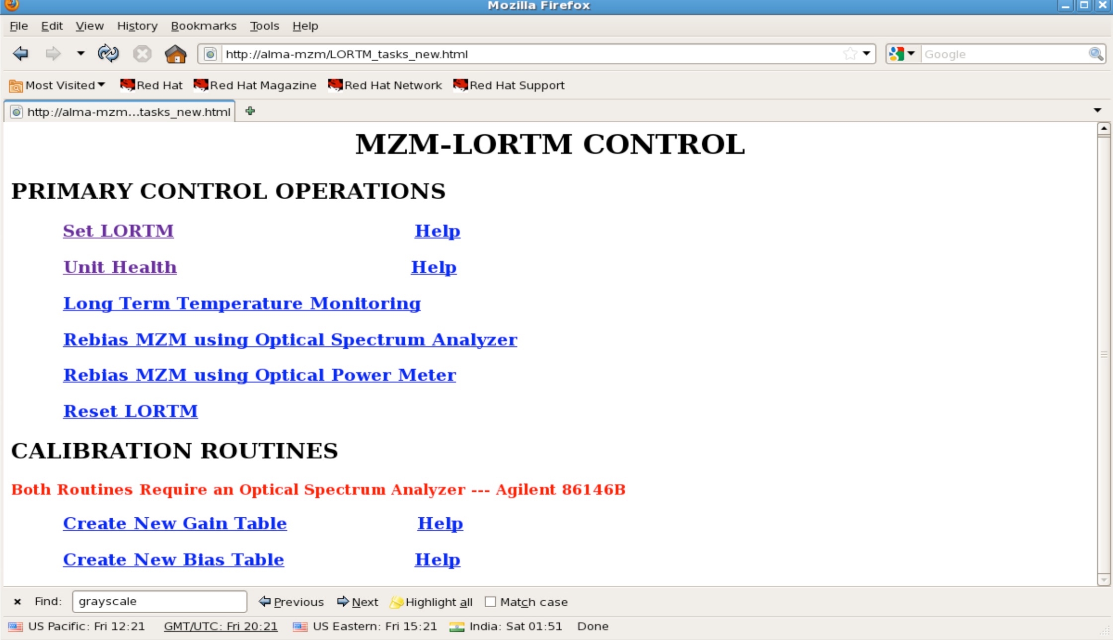   |

©2012, Institute of Astronomy and Astrophysics, Academia Sinica, All Rights Reserved.
Last Updated: 2012-06-03 | Contact: web asiaa.sinica.edu.tw | Privacy and Security Policy
Last Updated: 2012-06-03 | Contact: web
